
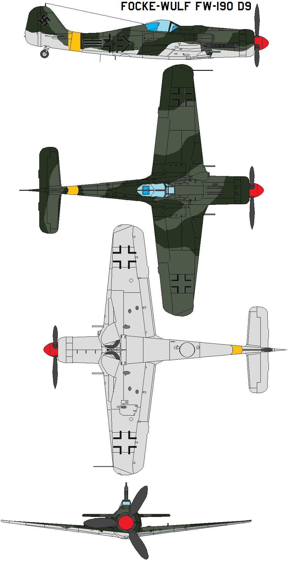
History: The Focke Wulf FW 190 was a true engineering masterpiece of its time, it served with distinction from its inception in 1941 until the final days of the war. Originally, the FW 190 was produced with a BMW 801 radial engine, the radial-engine powered version is the "A/F/G/S" model or "short nose" 190. The only reason the FW 190 was initially allowed to be produced is because it used a radial engine, virtually all of the Daimler Benz 600 series engines were allotted for Messerschmitt 109 and 110 aircraft. If the Focke Wulf had been designed to use the Daimler Benz engine, it would never have been produced. Because of a need for better performance at high altitudes, the FW 190A was re-equipped with the Jumo 213 series engine. Again, the Jumo 213 was chosen because the Daimler Benz engine was produced primarily for the Bf 109. It is interesting to note that the Jumo 213 was used in bomber aircraft not high performance fighters. Because the Jumo 213 is an inverted inline V-12 engine as opposed the BMW 801 radial design, fitting the Jumo 213 to the FW 190A airframe caused the appearance of the Focke Wulf fighter to change significantly. The nose of the aircraft was much longer, and in order to maintain the correct C.G., an extension plug was added between the tail section and the fuselage. These design changes give the FW 190D version a stretched look when compared to the FW 190A. The Focke Wulf FW 190D-9 "long nose Dora" became operational in the summer of 1944 and was universally acclaimed as the best fighter available to the Luftwaffe at that time, and is generally considered Germany's best mass-produced piston engine fighter aircraft of WWII. Approximately 700 FW 190D-9's were produced and served on western and eastern fronts in a variety of roles. Specifications (Fw 190 D-9) General characteristics * Crew: 1 * Length: 10.20 m (33 ft 5 1/2 in) * Wingspan: 10.50 m (34 ft 5 in) * Height: 3.35 m (11 ft 0 in) * Wing area: 18.30 m² (196.99 ft²) * Empty weight: 3,490 kg (7,694 lb) * Loaded weight: 4,350 kg (9,590 lb) * Max takeoff weight: 4,840 kg (10,670 lb) * Powerplant: 1× Junkers Jumo 213 A-1 12-cylinder inverted-Vee piston engine, 1,287 kW, 1,544 kW with boost (1,750 PS / 2,100 PS) Performance * Maximum speed: 685 km/h at 6,600 m, 710 km/h at 11,300 m (426 mph at 21,655 ft / 440 mph at 37,000 ft (11,000 m)) * Range: 835 km (519 mi) * Service ceiling: 12,000 m (39,370 ft) * Rate of climb: 17 m/s (3,300 ft/min) * Wing loading: 238 kg/m² (48.7 lb/ft²) * Power/mass: 0.30 - 0.35 kW/kg (0.18 - 0.21 hp/lb) Armament * 2 × 13 mm (.51 in) MG 131 machine guns with 475 rpg * 2 × 20 mm MG 151 cannons with 250 rpg in the wing root * 1 × 500 kg (1,102 lb) SC 500 bomb (optional) Add a Comment:
Cockpit details revealed:
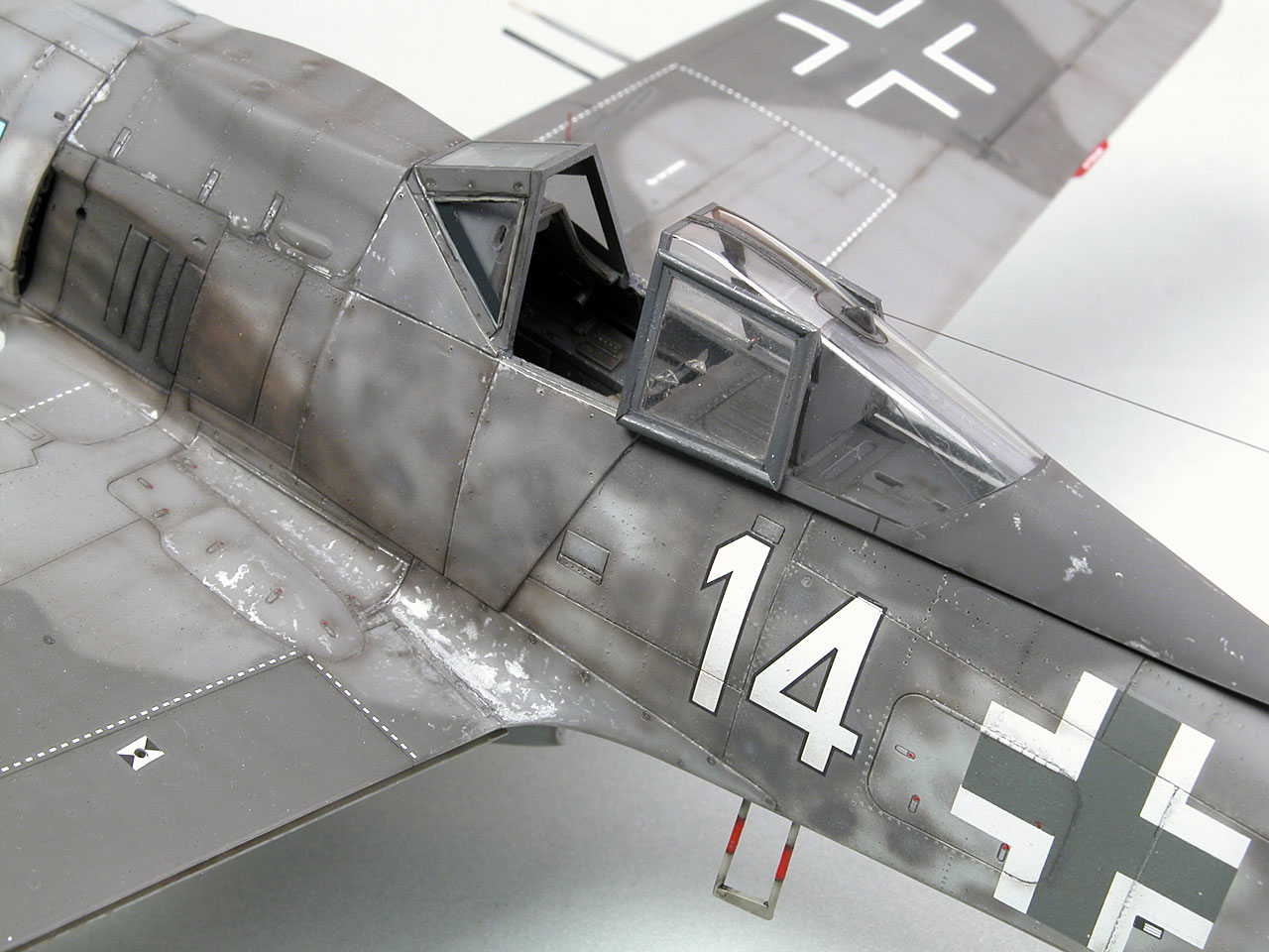


Cockpit details from IL-2 screen shots shown below in the following 3 images


The Cockpit details of the model generated from flight simulator screen images:


Irvine 120 2 stroke installed with the radial mount which was supplied by the manufacturer with the engine and attached to the plywood and oak sandwich spacer by 3 number 10 rubber well nuts providing a measure of vibration isolation.


With the batteries still to be installed the model balances about an inch behind the recommended center of gravity location which is indicated by the line made with a black felt marking pen. At this point I am estimating that a pound or so nose weight will be required before I will attempt to fly it.
Since writing these words I this model has successfully completed its maiden flight. I took the model to the flying field yesterday together with its forty five year stable mate; another FW 190 A which incidentally is a very good flyer with many flights logged over the years. The plan was to have three or four flights on the trusted 190 then switch out the flight battery and satellite receiver and install them in the new model, then do some serious shake-down testing. It all went so well when she became airborne on a high speed taxi run and rather than abort at 10 feet altitude
we decided to do a few circuits of the field and land. The landing was controlled into a 12 kilometer headwind with 15 degrees of flaps, so the touchdown speed was quite low with a gentle sink rate. To my surprise the port landing gear unit separated the wing cleanly and the plane slid to a stop on one wheel. I was prepared for the eventuality that reinforcing would have to be made. I have already filled the area with gap filling foam to help stabilize the built-up structural members; its a trick that I often perform for high stress areas and the results have usually been quite positive.

During what was to be a high speed taxi test the plane became suddenly airborne and the decision was made to do a circuit and land rather than to abort from 10 feet altitude.
The gap filling foam can be seen in the picture below as well as the pathetic glue area for securing the gear retract mounting beams.

The foam was cut away so that 1 X 1/2 X 2 inch oak beams were epoxied into the cavities and making sure that there was a good bond to the plywood box. Then the plywood gear mounting beams was epoxied and screwed to the oak beams. The repair seemed to holdup well during taxi tests, but are yet to be tested in a landing.
Since these pictures were shot we have changed the engine and installed a small gas engine (DLE 20) in place of the Irvine 120.
All my flying buddies are seriously into gas power for their models; they say give up on your big fuel guzzling glow engines and switch to a gasser that runs reliably on pump gas. With these arguments in mind I decided to replace the big Irvine 20 cc glow engine with a DLE 20 gas engine.