Monday, July 15, 2019

Messerschmidt's Wartime Aircraft


5 Messerschmitt Fighter Planes of WWII
  • INSTANT ARTICLES
  • MILITARY VEHICLES
  • WORLD WAR II
 Andrew Knighton


SHARE:FacebookTwitter
During the 1930s and 1940s, Messerschmitt made some of the most advanced and effective fighter planes in German service. They played an important part in the Second World War and in advancing technology in aerial warfare.

Bf109

The most famous German plane of the war, the Bf109, was created using features from a civilian plane, the Bf108. What had previously been used to power a four-seater touring plane now powered a one-seater fighter.
Upon entering service in 1937, the Bf109 soon proved its value. That November, one broke the world speed record for landplanes by flying at 379.38 mph. Bf109s went into action with the Condor Legion, German forces fighting in the Spanish Civil War. This provided pilots and engineers with more experience in operating the plane.
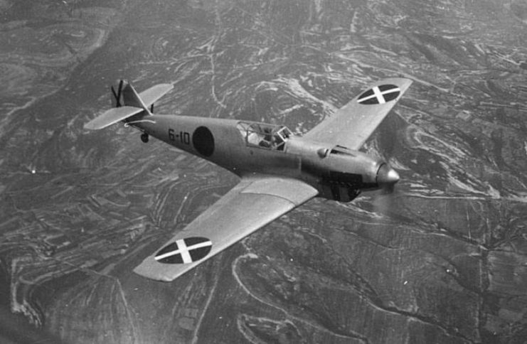


Bf 109A from the Condor Legion during Spanish Civil War (1936-1939)

Bf109s were widely used in the early stages of WWII, including the invasions of Poland and France and the Battle of Britain. The model E had a superior engine and weapons to the British planes it initially faced, which gave German pilots an edge in the air and made it infamous among its opponents.
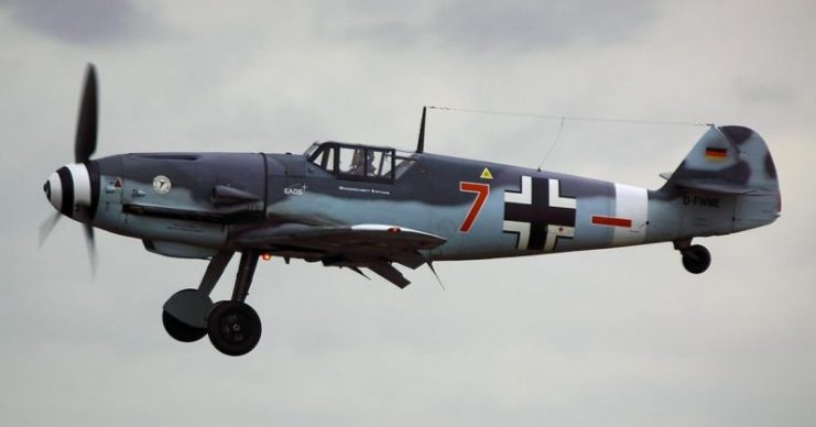


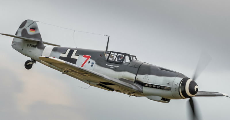
BF109 – RIAT 2010.Photo Tim Felce (Airwolfhound) CC BY-SA 2.0

Various models of Bf109 were deployed to fill different roles and counter advances in Allied aircraft. It remained in production after the end of the war thanks to the Czech firm Avia, whose factory survived the war. By the time production ended in the mid-1950s, over 35,000 Bf109s had taken to the skies.
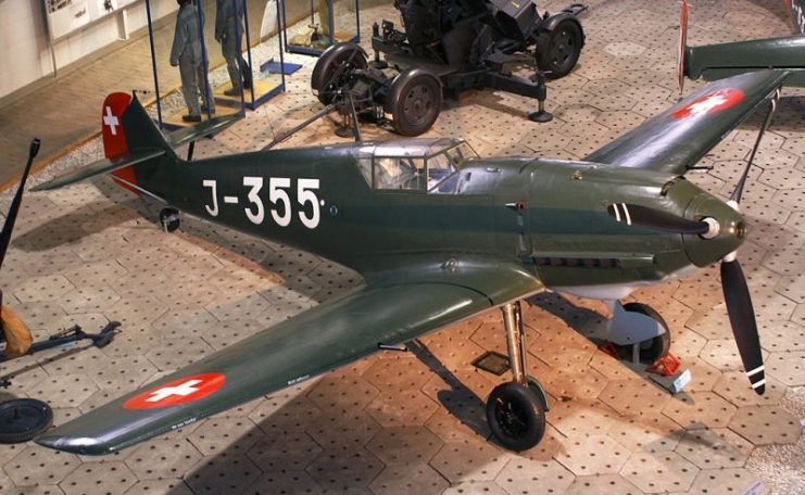


A Bf 109E-3 of the Swiss Air Force at the Flieger-Flab-Museum

Bf110

Designed around the same time as the Bf109, the Bf110 was a very different beast. Instead of being a dedicated interceptor, it was a combination of heavy fighter and light high-speed bomber. Its range and firepower would allow it to protect heavier bombers during runs into enemy airspace.
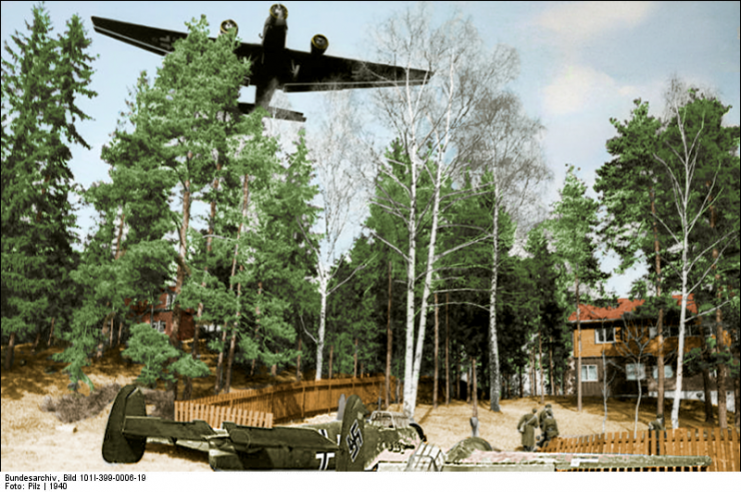


Messerschmitt Bf 110 of future night fighter ace Lt. Helmut Lent overshoot the runway in Oslo-Fornebu and came to rest in the garden of a house. A Junkers Ju 52/3m plane flies over the location. The photo has been taken by war reporters of the 5th Luftwaffe in Oslo1940.Photo: Pilz CC BY-SA 4.0

The Bf110 first went into combat during the invasion of Poland in September 1939. In December, Bf110s saw their first use in counter-bomber combat, shooting down 9 out of a flight of 22 RAF Wellingtons.
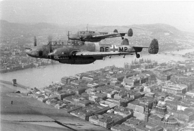


Bf 110s in flight above Budapest. 1944. Photo: Bundesarchiv, Bild 101I-669-7340-27 / Blaschka / CC-BY-SA 3.0

Following its early success, production increased, and 100 Bf110s per month were built in 1940. But the plane had a big problem: its lack of maneuverability made it vulnerable to advanced Allied fighters like the Spitfire and Hurricane.
Due to mounting losses, it was largely withdrawn from daytime service to become a night fighter. Once airborne radar was added, it became a deadly defender of Germany against nighttime raids. Its heavy weapons took down hundreds of Allied bombers. One pilot alone, Major Heinz-Wolfgang Schnaufer, claimed to have achieved 121 kills while flying a Bf110.
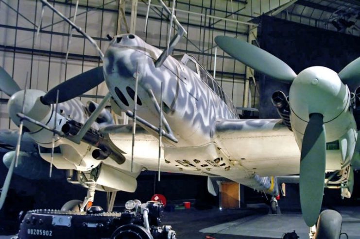


A Bf 110 G-4 night fighter at the RAF Museum in London.

Me410

The achievements of the Bf110 led to the development of a successor, which started out as the Me210. Despite test flights in which it stalled and proved unstable, the Me210 was put into production–only for this to be halted after 200 were built and more Bf110s being made instead.
Rather than abandon the plane, Messerschmitt engineers redesigned it. Renamed the Me410, the new version had a longer fuselage, automatic slats to stop it from stalling, and a more powerful engine.
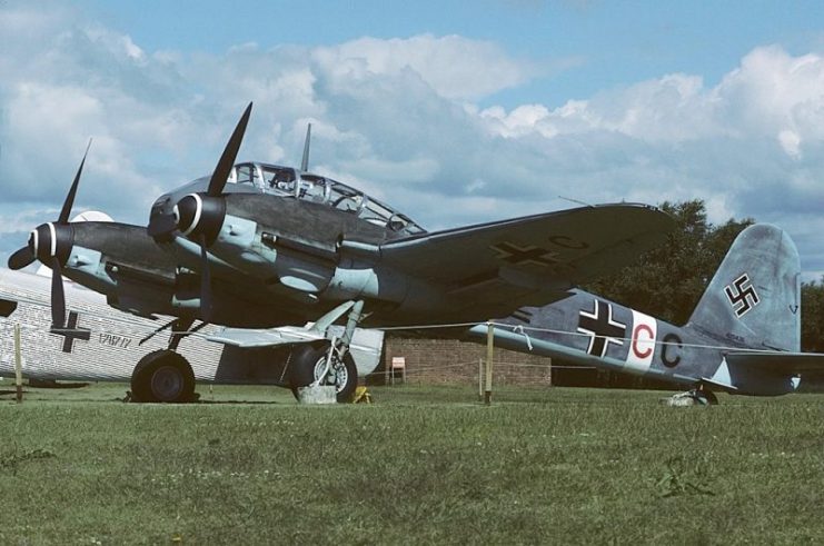


Messerschmitt Me-410A-1-U2 Hornisse, Germany – Air Force AN1139884.Photo Mike Freer GFDL 1.2

Like the Bf110, the Me410 could be used as a light bomber or heavy fighter. Entering service in January 1943, it was first used in nighttime bombing raids against Great Britain, and then to take out Allied bombers in the Mediterranean.
From early 1944 it was used to defend Germany against nighttime Allied bomber raids. It was also deployed as a night fighter against the Russians, who were now taking the offensive in the east.
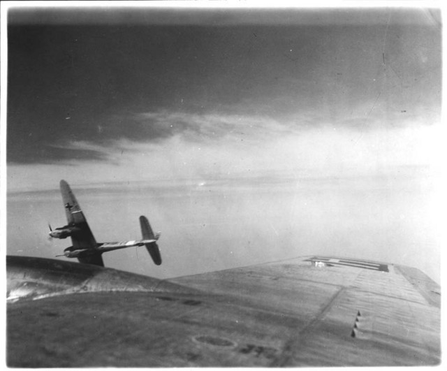


A Messerschmitt Me 410 with a BK 5 heavy autocannon peels off from attacking a 388th Bomb Group B-17 over Europe during the USAAF campaign against Germany, 1943

The heaviest weapon carried by an Me410 was the 50mm gun mounted beneath the fuselage of the Me104A-1/U4 model. This was devastating against enemy bombers but also nerve-wracking for the crew using it, thanks to its powerful recoil.
The Me410 was no better than the Bf110 it was meant to replace. Though over a thousand were made, production stopped in September 1944.

Me163
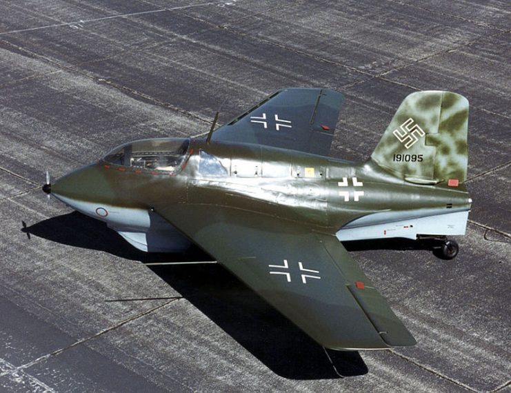


A German Messerschmitt Me 163B Komet rocket-propelled fighter (s/n 191095) at the National Museum of the United States Air Force, Dayton, Ohio (USA).

A high-performance rocket-powered plane, the Me163 was a truly radical design. Aside from its powerful high-tech engines, it had an unusual body shape and was one of the first planes to have swept wings. It was sometimes equipped with powerful experimental weapons, such as the SG 500 Jagdfaust, a set of vertical firing tubes triggered by the shadow of a bomber passing over the plane.
When it entered service in July 1944, the Me163 was twice as fast as anything the Allies could field against it. Small and agile, it was terrifying to face. Such high speeds initially proved problematic, as pilots had little time to fire before passing their targets. Swooping attacks from above proved to be the most effective tactic.
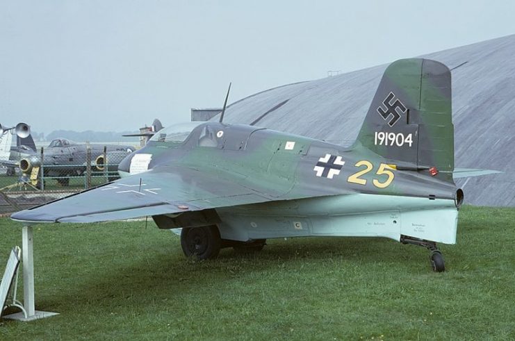


Messerschmitt Me-163B-1a Komet, Germany – Air Force AN1362828.Photo Mike Freer GFDL 1.2

Though its rocket made the Me163 deadly in combat, it could not be fired for long. The volatile fuel ran out after only seven and a half minutes of powered flight, after which the plane glided defenseless back to the ground. It was therefore only effective in a short-range air defense role.

Me262
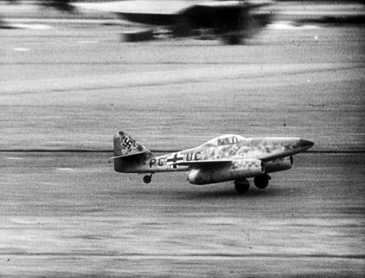


Me 262 Prototype in 1943.

Though the Me163 was interesting, the Me262 was Messerschmitt’s truly groundbreaking plane – the first ever operational jet aircraft.
The Me262’s development was delayed first by the German Command’s focus on proven technology, and then by the intervention of the Allies, who bombed the factories producing it in August 1943. Problems with the performance and reliability of the engines slowed down production, so it was over two years from the first test flight before the plane entered service in July 1944.
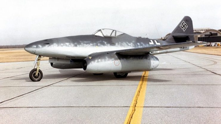


Messerschmitt Me 262A at the National Museum of the United States Air Force.

Equipped with 24 rockets and four 30mm cannons, the Me262 was deadly against enemy bombers, but its impact was limited by the difficulties of getting enough of them into the air. Though over 1,400 were made, fewer than 300 went into action. Lack of fuel, spare parts, and trained pilots kept some on the ground. Others were destroyed by Allied bombers before they could take flight.
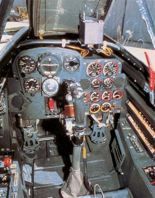


Me 262 cockpit

The Me 262 had a limited impact on the Second World War, but a huge effect on the development of military technology. It inspired designers across the world, shaping the design of jet fighters as they became the dominant force in aerial warfare.
Friday, July 12, 2019

The Mighty Red Barron


The Red Baron’s “other” Planes Yes He Had More Than Just One Fokker

  • INSTANT ARTICLES
  • WORLD WAR I
 Matthew Gaskill


SHARE:FacebookTwitter

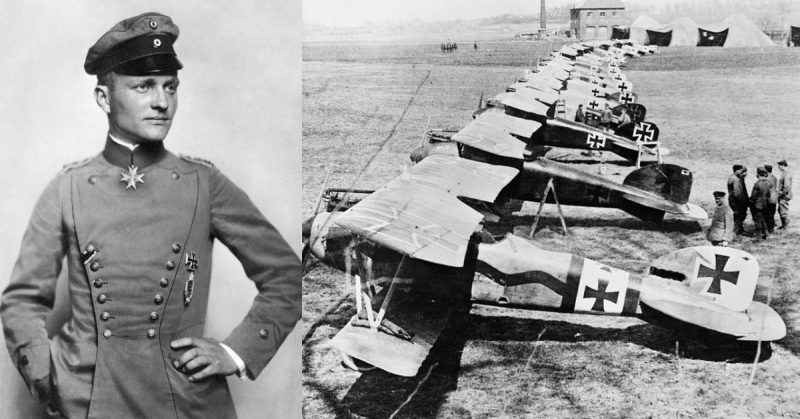
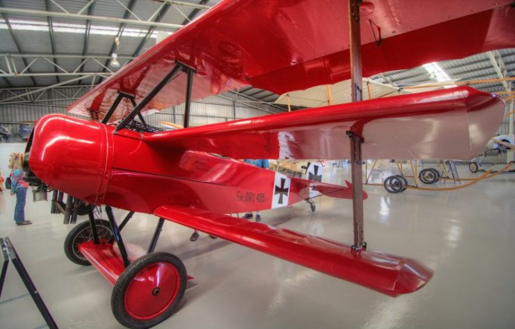
Though more than 100 years have passed and his record of aerial success was surpassed in WWII, to this day the flying ace that virtually everyone knows of is Manfred von Richthofen, “The Red Baron.” His red Fokker Dr.1 triplane is lodged in our collective memories. Actually, the plane is perhaps more widely known than his kill tally of eighty.
At air shows throughout the Western world, replicas of his famous red Dr.1 can be seen tooling through the sky, turning on a dime and chasing down the Sopwith Camels, Spads, and other Allied planes of the time.
“The Red Baron” flies regularly at Old Rhinebeck Aerodrome in Red Hook, New York. If the announcer suggested that the “Red Baron” had taken to the air, and the crowd didn’t see a red triplane, most would be confused and disappointed, but not those who really knew about “the Baron”.


Red Baron Triplane WW1. Photo: photobom CC BY 2.0

You see, most of Manfred von Richthofen’s kills did not come while he was piloting the famous triplane. Actually, just the last seventeen of his eighty kills came while he was flying the Fokker Dr.1.
While he did shoot down two planes in the three-winged forerunner of the Dr.1, the Fokker F.1, the others he achieved in aircraft from two different aircraft producers: Albatros and Halberstadt.


Fokker Dr.I. Replica of the famous Manfred von Richthofen triplane at the ILA 2006.Photo: Oliver Thiele CC BY 2.5

Before we discuss the “other” planes flown by the Red Baron, here is a brief bio of WWI’s “Ace of Aces”.
He was born in 1892. Both his father and mother were Prussian aristocracy. Manfred, along with his two younger brothers–one of whom, Lothar, became an ace in his own right–spent his youth in the typical ways of the rich and privileged of the 19th century. He studied with private tutors, but spent most of his time hunting, riding, and doing gymnastics. He was supposed to have excelled at all three.


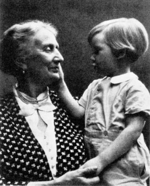
Kunigunde Dame von Richthofen, born von Schickfus und Neudorff, with her grandson Manfred von Richthofen


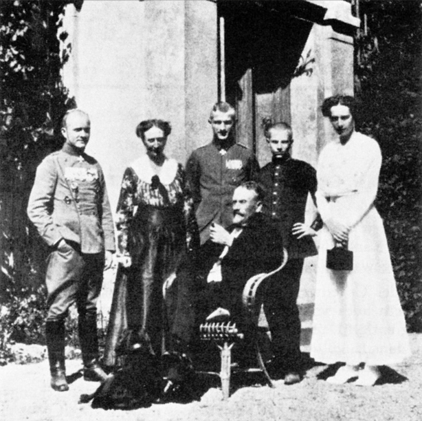
Family von Richthofen. Sitting in the middle Albrecht Freiherr von Richthofen, standing from left to right- Manfred von Richthofen, Kunigunde Dame von Richthofen, Lothar von Richthofen, Bolko of Richthofen and Ilse von Richthofen

When WWI began, Manfred served in the cavalry, being an accomplished rider. He saw action on both the Western and Eastern Fronts, but when the war bogged down into the trench warfare synonymous with the conflict, he grew bored and was eager to transfer to the air service, which he had become interested in as a boy.
He transferred to the Imperial German Army Air Service, known as the “Luftstreitkräfte” (“air combat force”) in May 1915. He underwent two months of training as a gunner and observer, and then served a short period in the summer and fall of 1915 flying observation missions first over Russia, and then France.


Manfred von Richthofen, the Red Baron.

At the time, the most famous German pilot was Oswald Boelcke, who wrote the “Dicta Boelcke,” a set of unofficial rules of aerial combat that still lays the groundwork for air to air combat today.
Richthofen met Boelcke, and this meeting convinced the young Baron to apply for fighter school. He also convinced his brother Lothar to join him. Lothar would end the war with 40 victories.
Manfred completed the course in one month and had a reputation as a below-average pilot. He crash-landed many planes initially and was lucky to have come out relatively unscathed. By comparison, his brother was considered the better pilot, and actually shot down more planes in a shorter time than Manfred, who was frequently out of action with wounds.


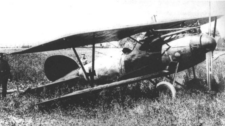
Richthofen’s Albatros D.V after forced landing near Wervicq. This machine is not an all-red one

Still, Richthofen learned from his mistakes, took the “Dicta Boelcke” to heart, and used the skills he learned as a hunter to become the greatest ace of them all.
Manfred is reported to have shot down a plane while he was a gunner on observation duty, and also a French Nieuport in his first days flying fighters, but those reports could not be confirmed. His first seventeen kills, starting with his first officially confirmed kill, came while he was flying the Albatros D.II aircraft on September 17, 1916. This was equal to the number he shot down flying the Fokker Dr.1.


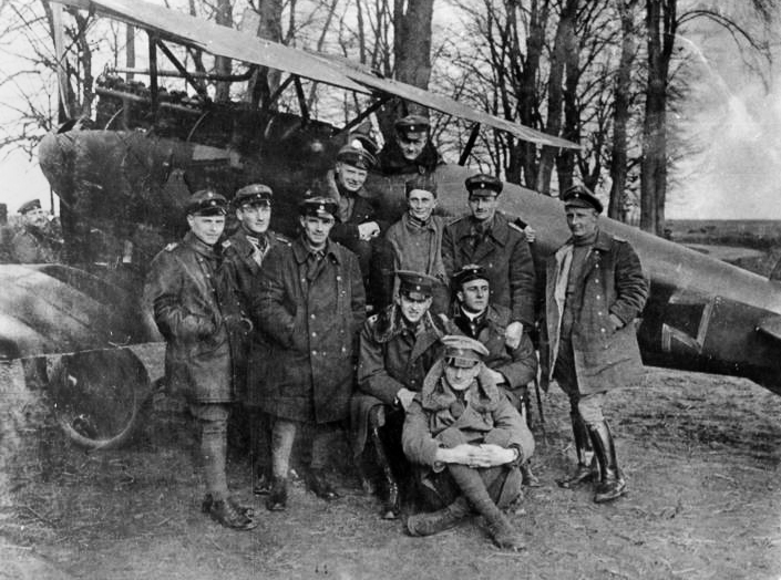
Manfred von Richthofen (in the cockpit) by his famous Rotes Flugzeug (“Red Aircraft”) with other members of Jasta 11. His brother Lothar is seated on the ground.

The Albatros D.II, as indicated by the name, was the second Albatros fighter. Obviously, the DII included changes and improvements, as both airplane design and flight science were growing by leaps and bounds through the necessity of war. Most of the improvements to the original D.I were made in response to pilots’ complaints about visibility.
The upper wing was moved forward and lower – the pilot could actually look over the wing at times when needing greater vision. The engines’ radiator was also low in the engine housing, which meant that when damaged, gravity helped it leak that much faster.


Albatros D.II

Eventually, the D.II had its radiator fitted into an airfoil-shaped housing on the top of the center wing. Still, if it was shot, scalding water could get in the pilot’s face. Later versions of the Albatros D series flown by Richthofen put the radiator in the front of the fuselage, canted to the right. This still made visibility tough, hence the lowered wing.
Other changes in the Albatros series included improvements in the strength and design of the wing struts, and improvements in engine efficiency and output, with a lightening of the weight of the plane relative to the output of the engine.


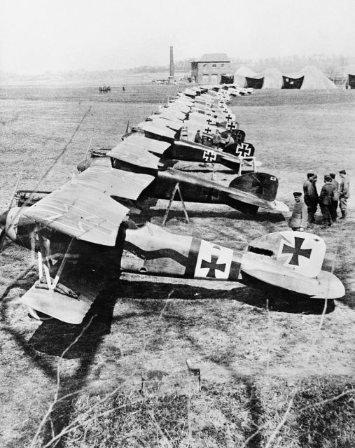
Albatros D.III fighters of Jasta 11 at Douai, France. The second closest aircraft was one of several flown by Manfred von Richthofen

The D.II had a top speed of 110 mph, a ceiling of nearly 17,000 feet and a rate of climb of almost 600 ft per minute–contrast that with the most famous “climber” in modern history, the F-16, which climbs at 50,000 ft per minute. A pilot could fly for about one and a half hours on full tanks.
The armament consisted of a variety of 7.92 mm guns throughout its service life. The plane was powered by a 6-cylinder Mercedes engine, had a wingspan of just under 28 feet and was 23.3 feet in length.
The D.III had a top speed similar to the D.II but a greater rate of climb. The D.V increased speed to 116 mph. Each had a higher ceiling than its predecessor.


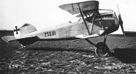
Albatros D.III (Oeffag) series 253, with later production rounded nose

From kill number 18 to kill number 52, Richthofen flew a collection of various Albatros and Halberstadt planes. Each Albatros iteration made improvements on the last, and it was while flying an Albatros that Richthofen adopted the color red for his plane.
He was not alone in painting his aircraft in unique colors. Many German pilots adopted the custom – most famously those of the famous “Flying Circus,” or Jagdgeschwäder (“Fighter Wing”) 11. Richthofen eventually rose to command this famous and successful group of pilots, who wanted both friends and enemies to know who they were.


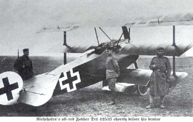
Richthofen’s all-red Fokker Dr

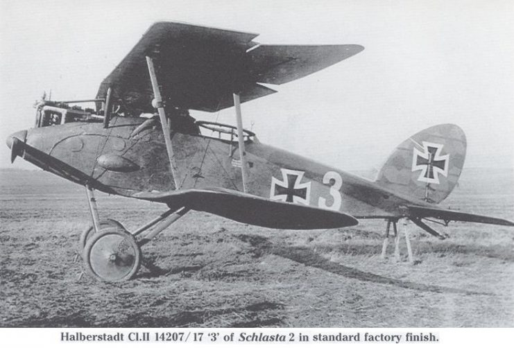
The Halberstadt D.II was similar in shape and design to the Albatros company’s planes. It had a thicker front section which tapered off radically towards the tail, though its streamlined appearance was marred visually by the radiator and top engine housing.
Many Allied planes, and later German planes, had their engines completely encased by the fuselage/cowling, to reduce damage and also mitigate the effect of the spray of oil and water from damaged engines.


German Halberstadt CL.II 14207 17 “3” of Schlasta 2. Note fairing for radio generator

The Halberstadt had been used early in the war, and Oswald Boelcke made his reputation in it. It had a top speed of only 93 mph, but was a solid plane. It also apparently turned well, as Boelcke pushed the plane to its limits in the search for advantage over his rivals.
Richthofen flew the plane near the end of its operational life – during WWI, advances in technology occurred almost weekly – and scored thirteen victories in it.


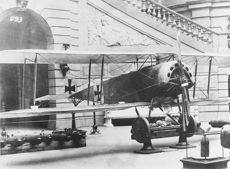
Boelcke’s Fokker D.III fighter on display. He scored eight victories with this plane between 2 and 19 September 1916.

Read another story from us: Aviation Innovator – Fokker’s 4 Leading Warplanes
The Red Baron also briefly flew the Fokker F.1 triplane, which had been made famous by the ace Werner Voss. Voss’ famous last battle, in which he held off eight British planes alone for a long time before finally being shot down, was fought in the unbelievably swift-turning F.1.
Improvements in the wing design of the F.1 spawned the Dr.1, which Richthofen made his own.


Build and Fly your own Fokker Dr1 From Famed British modeler P.E. Norman.s plans.


Tuesday, July 9, 2019

Stevens RingRat 100 Electric Control Line Build


Nostalgic good looks, meets light-weight rugged construction, and electric power system (with ground-adjustable throttle); setting the RingRat™ (100) apart from the competition. Docile enough for use as a control line trainer yet sporty enough for entry into stunting. Simple, quick building, all wood construction, complemented by clear photo illustrated instructions.

Wing span 18 in. | Wing area 100 sq. in. | Flying weight 5.5 oz.


Additional Details Features: Ideal entry into Control Line flying. Quiet clean electric motor fly in neighborhood parks, large backyards, and even indoors! Laser Engineered precision laser cut components for true interlocking construction. Light yet rugged airframe survives the rigors of training. Spring loaded landing gear smooths out the bumps and absorbs those less than perfect landings without damaging the air frame it’s attached to. Ground adjustable throttle combined with electric power system (see “You’ll Need” tab below) allows you to dial in a flying speed from mild to wild and flight duration from one to several minutes. Product Includes: Precision laser cut balsa and hardwood components. Pre-Bent shock absorbing landing gear, control horn, linkage, and bellcrank. Motor mount. Photo-illustrated assembly manual.

Required To Complete: SA Sport 300 (2204-14) Brushless Outrunner Motor and 7×3.5 Prop SA Sport 10A Brushless ESC Control Line Timer 325-350 mAh 7.4V LiPo Battery (20C Minimum) 1/2A control line handle and lines 1-2 rolls AeroFILM or AeroLITE covering Thin, Medium, and Thick CA glue Basic modeling tools.

Kit shortcomings :
Lack of a full size plan with this kit proved to be a definite drawback in building of this kit. It was almost impossible to align wing structural members with the hand build technique, especially the ribs;

The front and rear spar caps were far too flimsy to install in the tight fitting slots and routinely shattered under the finger pressure required to seat the spars into the ribs, these members would have fared much better had they been made of spruce of at the very lease hard balsa;

The construction feet on the bottom surface of the wing ribs which are supposed to aide in keeping the wing free of warps during construction were not well attached because of the very short sections of uncut material, the result was they kept braking off at an alarming rate and had to be reattached with glue throughout the wing buildup phase.


The heart of this little guy is the electronic timer which allows the control of its electric power without using any form of radio control for speed selection.


This is the magic bit that makes electric control line function. The control line timer governs every aspect of the flight. Delayed start, motor run up, flight time, and motor stop are all easily programmable. Our E-Zee timer is the finest on the market - imported from our friends in the UK.

View this video explaining its features, operation and setup.


Motor choice:


Description 1400KV UAV brushless motor Ideal for indoor 3D Flight, 220g and under Efficiency current (maximum): 2-6A (>74%) Current (no load): 0.3A The UAV Brushless Motor A2204/14 1400Kv is an excellent motor for planes up to 220 grams (8 oz) using 2 li-poly cells. Very lightweight at 19 grams including integral prop saver for APC 8x3.8 SloFly or APC 8x4 E propeller and integral firewall mount. Great for small 3D planes weighing around 6 oz, or aerobatic planes up to 8 oz. Use with a 10 Amp brushless ESC and small 7.4V lithium batteries in the 400 mah - 800 mah range. The motor features a 3 mm hardened steel shaft, dual ball bearings, integral prop saver for APC E props and integral firewall mount flange. Countersunk mounting holes have 31 mm spacing on centers.


Learning to Fly: http://www.mat.uc.pt/~pedro/ncientificos/f2/CLfaq.html
Choosing the Lines length : Thirty five feet is a good starting length. Some of the lower powered 1/2 As do well on 28 to 32 foot lines. Higher performance planes are a little easier to fly on 42'. I have a preference for .008" or .010" stranded steel lines. Stay away from the Dacron threads.

I built this CL model for my daughter who intended to fly it with her grandson after reminiscing of the days when she was a kid and flew my CL models for me because I couldn't do it myself because all the turning involved made me dizzy.


Monday, July 8, 2019

Team Kerr, Brackley and Gran, Handley Page v/1500 - The Great 1919 Transatlantic Air Race


Team Kerr, Brackley and Gran, Handley Page v/1500


Saturday May 10 1919

Morning Headlines:-


HANDLEY MACHINE REACHES ST. JOHN'S; Third British Transatlantic Flight Entry Now in Newfoundland. READY IN THREE WEEKS

New York Times featured article from May 10th 1919: Third British Transatlantic Flight Entry Now in Newfoundland. READY IN THREE WEEKS . Vice Admiral Kerr of Royal Air Force in Command of the Giant Bomber’s Crew. Special lo The New York Times. ST. JOHN’S N. P., May 10,-The Handley-Page bomber candidate for transatlantic flight prize honors, which arrived on the steamer Digby this morning:, was landed from the ship this after noon and.it is now loaded on freight cars at the railway .terminal, ready to be conveyed to Harbor Grace tomorrow morning. The consignment comprises altogether 100 packages, including a stock of gasoline. The crew of the machine, namely, Vice Admiral Mark Kerr. Major Brackley, and Major Grant of the Royal Air Force, and Lieutenant Taylor, meteorologist, and Lieutenant White, wireless operator; say they will proceed to Harbor Grace on Monday,- where a party of ten machinists have gone this evening. The work of assembling the machine will be started immediately and pushed to completion speedily, but probably three weeks will elapse before the plane is ready for a trial flight. As the Handley-Page machines are designed to operate in the open, extensive sheds will not be required as in the case of the Sopwith and Martinsyde machines, Protection from the weather will be needed only in putting together the smaller parts. The airdrome is been constructed at Harbor Grace under the direction of Lieutenant Robert Reid of the Royal Air Force, who won the Italian War Cross in operating against Austrian airmen in the Alpine country last Summer. He is the oldest son of Robert Reid, Vice President of the Reid Newfoundland Railway Company. and he has had all the facilities of that organization to assist him in a satisfactory working out of his project.

Vice Admiral Kerr of Royal Air Force in Command of the Giant Bomber's Crew. This team were the arch rivals of the Alcock and Brown Vickers' Team. and they had the best of everything; prepared airfield with vast stocks of Av-gas. Their own meteorologist and Rolls Rice technicians at their disposal. Their Handley Page 1500/100 4 engine bomber was equipped with powerful transmitters and receivers were capable of maintaining radio contact throughout the entire crossing.  And yet with all these advantages they missed the opportunity to fetch the prize that was theirs for the taking.

When the R34 arrived over Newfoundland at about 2 pm on 4 July 1919 on its East to West Trans Atlantic crossing destined for Mineola, Long Island, where it landed on 6 July. Vice Admiral Kerr and his HP giant bomber gave up on his Atlantic crossing dreams and set out from Harbour Grace to follow the R-34 to New York.
 
Learn more about this exciting expedition which occurred 100 years ago this year of 2019.


Monday, June 17, 2019

Gas/Electric Hybrid Bike Project

Canadian Power Assisted Bicycle Laws:

What Are E-Bikes?

Electric bikes often look like traditional bicycles, scooters, or even small motorcycles. Herein lies the problem – by simply looking at it, e-bikes are difficult to differentiate from other similar electric devices.
According to the Ontario Ministry of Transportation, e-bikes in Ontario have the following features :
  • Steering handlebars
  • Working pedals
  • An electric motor not exceeding 500 Watts
  • A maximum speed of 32 km/h
  • A maximum weight of 120 kg
  • A permanent label from the manufacturer in both English and French stating that your e-bike conforms to the federal definition of a power-assisted bicycle.
It is also illegal to modify your e-bike to make it faster or more powerful.
Precise Law:
POWER-ASSISTED BICYCLES
Consolidation Period: From December 6, 2018 to the e-Laws currency date.
Last amendment: 487/18.
This is the English version of a bilingual regulation.

Maximum weight

1. The unladen weight of a power-assisted bicycle must not be more than 120 kilograms.  O. Reg. 369/09, s. 1.

Wheel width, diameter

2. (1) The wheels of a power-assisted bicycle must not be less than 35 millimetres wide.  O. Reg. 369/09, s. 2 (1).
(2) The diameter of the wheels of a power-assisted bicycle must not be less than 350 millimetres.  O. Reg. 369/09, s. 2 (2).

Battery and motor

3. (1) The battery and motor of a power-assisted bicycle must be securely fastened to the bicycle to prevent them from moving while the bicycle is in motion.  O. Reg. 369/09, s. 3 (1).
(2) The motor of a power-assisted bicycle must cease to propel the bicycle forward if pedalling stops, the accelerator is released or the brakes are applied. O. Reg. 487/18, s. 1.

Electric terminals

4. All electric terminals on a power-assisted bicycle must be completely insulated and covered.  O. Reg. 369/09, s. 4.

Brakes

5. The brakes of a power-assisted bicycle must be capable of bringing the bicycle, while being operated at a speed of 30 kilometres per hour on a clean, paved and level surface, to a full stop within nine metres from the point at which the brakes were applied.  O. Reg. 369/09, s. 5.

No modifications

6. A power-assisted bicycle must not be ridden on, driven or operated if it has been modified after its manufacture in any way that may result in increasing its power or its maximum speed beyond the limits set out in clause (d) of the definition of “power-assisted bicycle” in section 2 of the Motor Vehicle Safety Regulations made under the Motor Vehicle Safety Act (Canada).  O. Reg. 369/09, s. 6.

Good working order

7. A power-assisted bicycle must not be ridden on, driven or operated unless it is in good working order.  O. Reg. 369/09, s. 7.
8. Omitted (provides for coming into force of provisions of this Regulation).  O. Reg. 369/09, s. 8.


Located this Schwinn Balloon Tire Beach Cruiser bike on Marketplace in excellent condition for 120 dollars that I intend to transform into my cottage bike. Since the cottage is located in a remote hilly region of Eastern Ontario I set out to endow our bike with lots of hill climbing ability.


Watch this video clip to follow along as I turn the old Beach Cruiser into a fun Hybrid Bike.


It been a while, working to get the kinks out of the chains and sprockets for this installation but we are beginning to gain some confidence in its reliability.


Instead of getting better the chain problem steadily grew worse until while peddling along the drive train suddenly seized. After considerable effort we were able to free it enough to get the engine started and motored home. At this point we decided that before another ride we needed to get to the bottom of the drive train problem.

Because the chain worked well during the ride home it was ruled out as the cause of seizure problem and began concentrating on the clutch.

The first test was to run the bike by the electric motor with the rear wheel off the ground and the clutch disengaged. The drive train ran smoothly for a while then it slowed and chattered sporadically then suddenly the engine started and began to run although the clutch lever remained in the disengaged position. This had happened a few times before while during e bike riding conditions but while troubling it had not seemed important enough to investigate further. The sudden starting event was replicated several times so a clutch tare down was initiated.

A Google search produced several helpful videos and discussion group topics which proved helpful and progress went quickly until the clutch removal stage was reached. It was clear that the clutch plate was not coming off without the aid of a gear puller.

    One was ordered from an Ebay seller then another from a local supplier just to beat the lengthy delivery time dilemma. Thinking about the picture of the tool I began to realize that there was one supplied in the Gas Bike Kit stored away in the basement.

Employing the gear puller the clutch plate finally popped off the shaft just before we were running out of threads on the center screw of the puller. It was not without a lot of prying and applying of heat from a blow torch to the big gear retaining ring did the clutch plate separate from its base plate.


The retaining ring is actually also the inner race for a bearing to aid the free turning of the clutch plate while disengaged. The bearing consists of many free ball bearings which are meant to be retained by the inner race and the inner ring of the clutch plate's bevel gear.

The area under the retaining ring/bearing was found to be badly pitted and galled with smeared metal stuck or welded to its surface. There were no more than a half dozen ball bearings floating around intact, the rest presumably accounted for the smashed metal debris that had caused my clutch to completely seize up.

Upon viewing the sad condition of the clutch plate assembly I immediately placed an order for the complete clutch rebuilding kit from Motorized Bicycle Canada.

Since the wait was going to be at least a few days and the October weather was pleasant enough for biking we decided to clean up the damaged back plate and smear the bearing surface with a little grease. Taking care to not apply too much for fear contaminating the friction surfaces with lubricant, which certainly would cause a slipping clutch.

The clutch was quickly reassembled without much difficulty, except for the flower nut which would not thread onto the actuator pin which could have been damaged during the clutch removal procedure. Beveling the end of the actuator pin with a Dremel grinding wheel removed the damage enough for the flower nut to thread onto the actuator.

Clutch adjustments were performed to optimize the drag under disengaged and slippage under engaged conditions.

A twelve kilometer shakedown ride was promptly completed where the bike preformed flawlessly. The only change noted was the jump starts caused the back tire to slide some on the wet gravel surface, this had never been observed previously.  The only possible cause for this may be previously the engine was leaking compression because of loosely fitting spark plug.


  1. The Map-My-Ride Analysis video of the Shake-Down Ride