There are two main schools of thought amongst airmen; those that a spouse to the belief that it is safer to stop before landing and those that prefer to land before stopping. The helicopter is one flying machine that conforms to the first school.
Helicopters have been around a long time. In fact, the first helicopter accepted as such was the Focke-
Wulf Fw 61, created in 1936. Sikorsky later mastered helicopters. The term “helicopter” comes from hélicoptère in French, after Gustave Ponton d’Amécourt coined it in 1861. He took it from the Greek helix. It didn’t take long for someone to imagine a car with a helicopter rotor above it.
The flying car animated picture above is a mashup of the following flying cars. 1917 Curtiss Autoplane 1937 Waterman Aerobile 1947 ConVairCar Model 118 1966 Aero-Car 1971 AVE Mizar 2009 Terrafugia Transition 2014 AeroMobil 3.0 2017 AeroMobil 4.0
The fixed wing aeroplane on the other hand usually lands before stopping and to do that safely requires large expansive surfaces such as airports to operate from. Airports are generally associated with large urban centers, served with all kinds of services such as car rental check out counters so, no need for a car that flies in this case. As an flyer myself I have the idea that the most useful form of flying car would be one that stops before landing such as a helicopter or auto-gyro that exhibits also, good driving characteristics with a ground range of about 200 miles. The flying feathers should be easily detachable and the drive-able module electric powered. The transportation standards have become so extensive over the years for cars with requirements for crash worthy bumpers, airbags, impact crash testing, roll over standards etc have made it impractical to develop a flying car that complies with airworthiness and roadworthiness standards simultaneously, witness the case where the selling price for the Aeromobile has risen from 200,000 dollars to 400,000 during its development phase.
In my opinion it would make more sense to design the road vehicle comply with standards as a three wheel motorcycle.
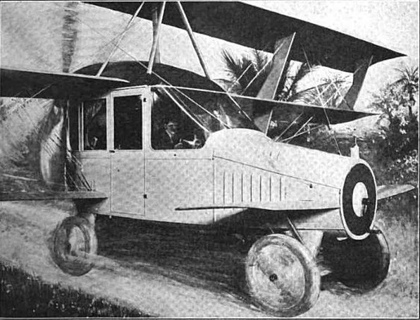
1917 Curtiss Autoplane
Glen Curtiss invented and built the first flying aerial limousine - the Curtiss "Autoplane."
Curtiss "Autoplane" 1917
The Pan American Aeronautical Exposition of 1917, held in New York's gaudy Grand Central Palace exhibition hall, represented "the biggest and best display of airplanes, aeronautic motors and aerial accessories and supplies ever gotten together on this continent. It was one of the most interesting exhibits at the Exposition.
The Autoplane quickly picked up the nickname "aerial limousine" because the pilot sat at the steering wheel and the two passengers in seats behind him.
The body is a combination of the motor car and aircraft practice, and follows very closely the lines of a modern limousine or coupé car-body. It is constructed mainly of aluminum, the windows being of celluloid. Elaborate upholstery and tapestries are employed for the interior, which accommodates two passengers in the rear and a "chauffeur" forward. Right in front is a circular radiator, through which passes a starting handle for the engine, a Curtiss OX-5 100 h.p., which is located under the bonnet. From the engine, power is transmitted through a shaft, extending to the rear of the body, to the four-bladed propeller located at the top.
There is a pair of wheel fore and aft, mounted in a similar way as on the Curtiss tractor triplane. The axle of the front pair, however, follows motor car practice in that the wheels are pivoted and connected to the control so as to enable the machine to be steered on the ground.
The triplane wings are also similar to the triplane tractor, except that they are staggered and the lower plane is of shorter span. The wing section is "F-2" with an angle of incidence of 4º and a dihedral angle of 3º to the lower plane. The top plane is connected to a cabane mounted on the roof of the "car," whilst the center and lower planes are attached to the body itself. Covered-in K-shaped inter-plane struts separate the planes, and interconnected ailerons are fitted to top and center planes.
The tail is carried by a pair of horizontal tubular outriggers attached to the center plane. The tail surfaces consist of a rectangular horizontal stabilizer, divided elevators, rudder and triangular vertical fin. Mounted on the bonnet, just above the front wheels, is a small plane. The general dimensions are as follows: - Span (top and center) 40 ft. 6 ins., (bottom) 23 ft. 4 ins.; chord (top and center) 4 ft., (bottom) 3 ft. 6 ins., gap, 3 ft. 3 ins.; stagger, 11 ins.; overall length, 27 ft.; height 10 ft.; width of body, 3 ft. 6 ins.; speed range, 45-65 m.p.h.; useful load, 710 lbs.
Development of the Autoplane was superseded by the war effort when America entered World War 1 only 2 month after the unveiling.
1937 Waterman Aerobile

Waldo Waterman's first flying wing aircraft was the unofficially named Waterman Whatsit, a pusher configuration low swept-wing monoplane with fins near its wing tips. The Whatsit also featured a wing-mounted tricycle undercarriage and a trim foreplane. Powered by a 100 hp (75 kW) Kinner K-5 5-cylinder radial pusher engine, it first flew in 1932.]
In May 1935 Waterman completed a submission to the government funded Vidal Safety Airplane competition. This was the Arrowplane, sometimes known as the W-4. This adopted a similar layout to the Whatsit but had a strut-braced high wing on a blunt-nosed, narrow fuselage pod with a tricycle undercarriage mounted under it. Its wings had wooden spars and metal ribs and were fabric covered, with triangular endplate fins carrying upright rudders. Its fuselage was steel framed and aluminium covered. It was powered by a 95 hp (71 kW) inverted inline 4-cylinder Menasco B-4 Pirate pusher engine mounted high in the rear of the fuselage. The Arrowplane was not intended for production or to be roadable, but its success in the Vidal competition encouraged Waterman to form the Waterman Arrowplane Co. in 1935 for production of a roadable version. The resulting Arrowbile, referred to by Waterman as the W-5, was similar both structurally and aerodynamically to the Arrowplane, though the fins differed in shape, with rounded leading edges and swept-back rudder hinges. For road use the wings and propeller could be quickly detached. The main other differences were in engine choice, the need to drive the wheels and to use conventional car floor-type controls on the road. The air-cooled Menasco was replaced by a water-cooled engine as used by most cars. Waterman modified a 6-cylinder upright, 100 hp (75 kW) Studebaker unit and placed it lower down in the pod, driving the propeller shaft at the top of the fuselage via six ganged V-belts with a 1.94:1 speed reduction. The radiator was in the forward fuselage, fed from a duct opening in the extreme upper nose. On the ground the engine drove the main wheels through a differential gear, as normal, and the car was steered by its nosewheel. The wheels were enclosed in fairings, initially as a road safety measure. Instead of removing the propeller for the road, it could be de-clutched to prevent it windmilling the engine at speed. The wheel in the two-seat cabin controlled the Arrowbile both on the road and in the air. Outer wing elevons moved together to alter pitch and differentially to bank. The rudders, interconnected with the elevons when the wheel was turned, moved only outwards, so in a turn only the inner rudder was used, both adjusting yaw as normal and assisting the elevon in depressing the inner wing tip. This system had been used on the Arrowplane as a safety feature to avoid the commonly fatal spin out of climb and turn from take-off accident but the raked rudder hinge of the Arrowbile provided the banking component even from a nose-down attitude. There were no conventional flaps or wing mounted airbrakes but the rudders could be operated as brakes by opening them outwards together with a control independent of the wheel. The cabin interior was designed to motor car standards, with easy access and a baggage space under the seats. The Arrowbile first flew on 21 February 1937, making it a close contemporary of the Gwinn Aircar, and a second prototype with a number of minor modifications followed. Studebaker were interested in the Arrowbile because of the use of their engine and ordered five. The third Arrowbile was the first of this order. However there was little market response and the line was halted in 1938, with no more production aircraft completed. The production aircraft had several changes, some of which aimed to emphasise the similarities with cars; there was a radiator grille with a single headlight centrally above it and also car type doors and petrol filler cap. The fourth Aerobile was completed as a conventional, non-roadable aircraft; Waterman initially retained the Studebaker engine but in 1941 replaced it with an air-cooled 120 hp (89 kW) Franklin. In 1943 he modified the wings with slotted flaps and later still replaced the braced wing with a cantilever one, using the wing from the unbuilt fifth aircraft. The last, sixth aircraft was not completed and flown until May 1957. It was a three-seat, roadable version powered by a water-cooled 120 hp (89 kW) Tucker-Franklin. This was cooled by radiators on each side of the engine, fed air by fuselage side scoops. In the absence of the forward radiator the nose was remodelled, becoming shorter and blunter. The fins were also altered so that the upper and lower leading edges met at an acute angle. At some point this particular Arrowbile was renamed the Aerobile, though it was not a name that Waterman used.
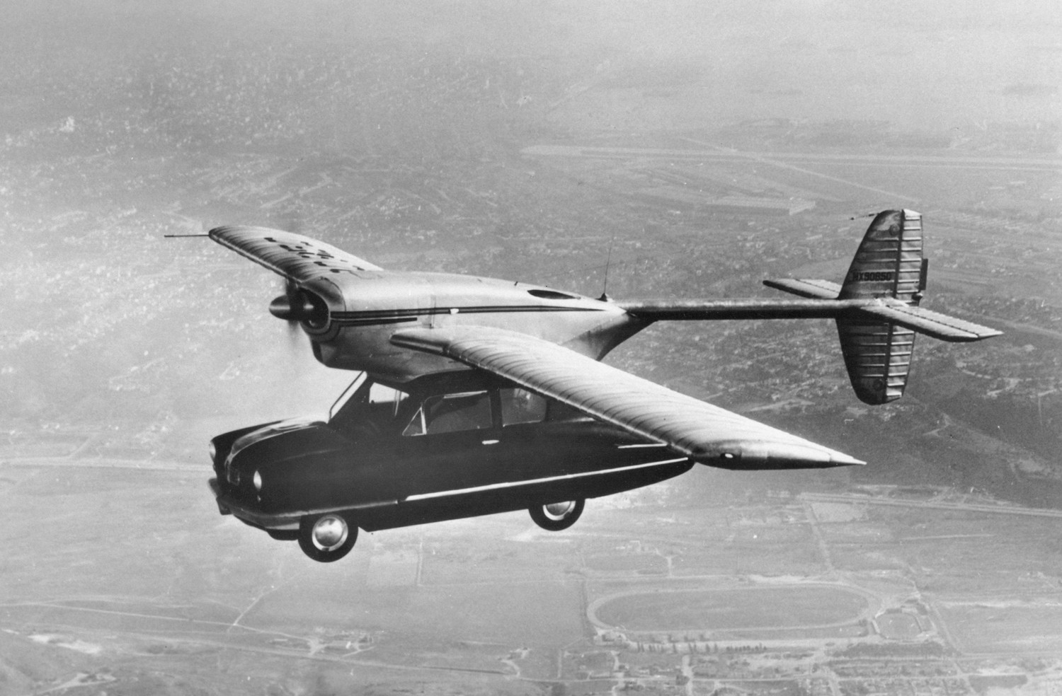
1966 ConVairCar Model 118

Consolidated Vultee Aircraft (later Convair) was seeking entry into the post-war aviation boom with a mainstream flying car. Theodore P. "Ted" Hall had studied the concept of a flying car before World War II, with Consolidated unsuccessfully proposing the idea for use in Commando type raids. Following the end of the War, Hall and Tommy Thompson designed and developed the Convair Model 116 Flying Car featured in Popular Mechanics magazine in 1946, which consisted of a two-seat car body, powered by a rear-mounted 26 hp (19 kW) engine, with detachable monoplane wings and tail, fitted with their own tractor configuration 90 hp (67 kW) Franklin 4A4 engine driving a two bladed wooden propeller. This flew on July 12, 1946, completing 66 test flights.Hall subsequently designed a more sophisticated development of the Model 116, with a more refined car body and a more powerful "flight" engine. A 25 hp (19 kW) Crosley engine was in the rear, powering the plastic-bodied 4-seat car and a 190 hp (142 kW) Lycoming O-435C was used for the powerplant of the aircraft. A lofty production target of 160,000 was planned, with a projected $1,500 price tag. Convair anticipated that the Model 118 would be purchased in large numbers to be rented at airports.Operational history[edit]
Test pilot Reuben Snodgrass flew the prototype, registration No. NX90850, for the first time on November 15, 1947. On November 18, 1947, while on a one-hour demonstration flight, it made a low fuel forced landing near San Diego, California destroying the car body and damaging the wing. The pilot, who escaped with minor injuries, reportedly took off with little or no aviation fuel aboard. Although the fuel gauge he had visually checked during the pre-flight check indicated that the tank was full, it was the automobile's fuel gauge, not the aircraft's gauge. Using the same wing and another car body, the second prototype flew again on January 29, 1948 piloted by W.G. Griswold, but enthusiasm for the project waned and Convair cancelled the program. The rights reverted to Hall, who formed T.R Hall Engineering Corp., but the Model 118 in its new incarnation never achieved production status.
1971 AVE Mizar


The prototypes of the Mizar were made by mating the rear portion of a Cessna Skymaster to a Ford Pinto.The pod-and-twin-boom configuration of the Skymaster was a convenient starting point for a hybrid automobile/airplane. The passenger space and front engine of the Skymaster were removed, leaving an airframe ready to attach to a small car. AVE planned to have their own airframe purpose-built by a subcontractor for production models, rather than depending on Cessna for airframes. According to Peterson's Complete Ford Book, by mid-1973, two prototypes had been built and three more were under construction. One prototype was slated for static display at Galpin Ford, owned by AVE partner Bert Boeckmann of Sepulveda, California. The other prototype, fitted with a Teledyne Continental Motors 210 horsepower (160 kW) engine, was unveiled to the press on May 8, 1973. It then began a series of taxi tests at Van Nuys, California. AVE made special arrangements to do flight testing at the U.S. Navy's test facilities at Point Mugu, California. AVE stated that FAA certification flights were underway in mid-1973. The Mizar was intended to use both the aircraft engine and the car engine for takeoff. This would considerably shorten the takeoff roll. Once in the air, the car engine would be turned off. Upon landing, the four-wheel braking would stop the craft in 525 feet (160 m) or less. On the ground, telescoping wing supports would be extended and the airframe would be tied down like any other aircraft. The Pinto could be quickly unbolted from the airframe and driven away. Production was scheduled to begin in 1974. AVE had stated that prices would range from US$18,300 to US$29,000. On a test flight from Camarillo Airport in California on August 26, 1973, according to test pilot Charles "Red" Janisse, the right wing strut base mounting attachment failed soon after takeoff. Because turning the aircraft would put too much stress on the unsupported wing, Janisse put the aircraft down in a bean field. After the roadway was closed to traffic, Janisse drove the otherwise undamaged aircraft back to the airport.
On September 11, 1973, during a test flight at Camarillo, the right wing strut again detached from the Pinto. With Janisse not available for this test flight, Mizar creator Smolinski was at the controls. Although some reports say the Pinto separated from the airframe, an air traffic controller, watching through binoculars, said the right wing folded. According to Janisse, the wing folded because the pilot tried to turn the aircraft when the wing strut support failed. Smolinski and the Vice President of AVE, Harold Blake, were killed in the resulting fiery crash.
Even though the Pinto was a light car, the total aircraft without passengers or fuel was already slightly over the certified gross weight of a Skymaster. However, in addition to poor design and loose parts, the National Transportation Safety Board reported that bad welds were partly responsible for the crash, with the right wing strut attachment failing at a body panel of the Pinto.
2009 Terrafugia

The experimental Transition Proof of Concept's first flight in March 2009 was successful and took place at Plattsburgh International Airport in upstate New York using U.S. Federal Aviation Administration (FAA) tail number N302TF. First customer delivery, as of March 2009, was originally planned to take approximately 18 months and occur in 2011. On July 1, 2010 it was announced that the Terrafugia Transition had been granted an exemption from the FAA concerning its Maximum Takeoff Weight (MTOW) allowing the Transition to be certified with a take-off weight up to 1,430 pounds (650 kg); the limit matches the MTOW for amphibious light-sport aircraft. The extra 110 pounds (50 kg) granted by the exemption provides more weight allowance for the mandatory road safety features such as airbags and bumpers.
Oshkosh July 2008, Proof of Concept
Oshkosh July 2011, Production Prototype
The proposed design of the production version was made public at AirVenture Oshkosh on July 26, 2010. Aerodynamic changes revealed included a new, optimized airfoil, Hoerner wingtips, and removal of the canard after it was found to have an adverse aerodynamic interaction with the front wheel suspension struts; furthermore, the multipurpose passenger vehicle classification from the NHTSA removed the requirement for a full width bumper that had inspired the original canard design. On November 16, 2010 the U.S. National Highway Traffic Safety Administration (NHTSA) published Terrafugia's petition for a temporary, three-year hardship exemption from four FMVSS standards in the Transition. Terrafugia requested to use lighter weight motorcycle tires instead of RV tires, polycarbonate for the windshield and side windows, basic airbags instead of advanced, dual stage airbags and to not include an electronic stability control system. The NHTSA granted all of the requested exemptions on June 29, 2011, but limited the stability control and airbag exemptions to one year. In June 2011, a delay was announced and Terrafugia's CEO estimated that about another 18 months would be required before first customer delivery in "late 2012", but this was not achieved. December 2011 saw the base price increased to US$279,000 from an initial price of US$194,000. After undergoing drive tests and high-speed taxi tests, the production prototype completed its first flight on March 23, 2012 at the same airport in Plattsburgh, New York that was used for the Proof of Concept's flight testing. The production prototype then made its auto show debut at the 2012 New York International Auto Show in April 2012. In June 2012, Terrafugia announced that the Transition had completed the first of six phases of flight testing. By July, the second phase of testing was underway, expanding the performance envelope in the sky and continuing drive testing on the ground. In January 2013, development continued and the company announced that it might be necessary to construct a third, completely new prototype, due to the large number of modifications required. The modifications to date are said to appear to have improved the previous handling characteristics. By March 2014, the design of the third, updated prototype had progressed to finalization of the major structural members and a statement to investors said that it would be used in final compliance testing for certification before the first customer delivery which was then estimated to take at least another 18 months and occur "in 2015". By April 2014, 12 two-person test flights had taken place; this was the first time that anyone other than Terrafugia's chief test pilot had flown the Transition.As of 22 August 2014, first customer delivery was hoped for in about 18 months "in the second quarter of 2016." In December 2014 the company asked the FAA to allow the Transition to be operated at a gross weight of 1,800 lb (816 kg) instead of the light-sport aircraft maximum weight of 1,320 lb (599 kg) and have a stall speed of 54 kn (100 km/h; 62 mph) instead of the category maximum of 45 kn (83 km/h; 52 mph). The company indicated that the increases were required to allow inclusion of structures to meet FMVSS ground operation safety regulations. The company had previously been granted an increase in gross weight of 110 lb (50 kg) and another LSA aircraft, the ICON A5, was granted a 250 lb (113 kg) exemption to meet FAA spin resistance requirements; this new application would increase the Transition's allowed weight by a total of 480 lb (218 kg) or 36%. During consultations the request for the weight increase was supported by the General Aviation Manufacturers Association, the Experimental Aircraft Association, the Aircraft Owners and Pilots Association and the Light Aircraft Manufacturers Association. Only a few individuals expressed opposition to the request. The exemption was granted by the FAA on 19 June 2016.In April 2015 the company announced that parts were being built for the third version of the aircraft, and that current planning estimated the first customer delivery after roughly two years. Terrafugia COO/VP of Engineering Kevin Colburn also stated that the company has changed the price estimate from $279K to between $300K and $400K. In November 2015, the company announced that the third version of the Transition was being tested with a Rotax 912is engine, rather than the Rotax 912ULS that the second prototype had flown with. As of April, 2017, the company's website says "Today, Terrafugia is finalizing production vehicle design and compliance testing in preparation for vehicle deliveries within the next three years."
2014 Aeromobile 3

AeroMobil, a Slovakian company, plans to start selling its creation, the AeroMobil 3.0, in 2017.
The company claims on its site that the vehicle "transforms in seconds from an automobile to an airplane" by using "existing infrastructure created for automobiles and planes."
The vehicle is gas-powered and has wings that fold, which allows it to be parked like a car, though it is nearly 20 feet long.
The company's web site features a video where the AeroMobil 3.0 drives out of a hangar and goes down a highway, sharing the road with regular cars until it arrives at an airstrip. The car then unfolds its wings and takes off from a stretch of grass, rather than a paved tarmac, and flies through the air like any other small airplane.
AeroMobil spokesman Stefan Vadocz said his company hasn't nailed down an exact price because it's not ready yet.
"The prototype is a work in progress," he said in an email. But he said to expect the price to be several hundreds of thousands of euros, somewhere in between a sports car and a light sports aircraft.
Related: Challenger Hellcat production suspended
The vehicle seats two people -- the pilot and a passenger - and its single propeller is located to the rear of the plane.
The company said the car's top speed on the road is at least 99 mph and while flying is at least 124 mph. It can fly for 435 miles before running out of gas.